


Modular Power Supply Solutions for Military R&D: Enabling High-Precision Radar, Signal Generators, and Oscilloscopes
1. Stringent Power Demands in Military R&D Test Systems
Military research institutes and defense technology laboratories rely on highly specialized test systems such as radar, signal generators, and oscilloscopes, each requiring high-precision, high-reliability power delivery. These power systems are subject to conditions far beyond typical commercial applications:
1.1 Challenges in Harsh Military Environments
-
Temperature Extremes: Operating range from –55°C to +85°C, requiring components with extended temp ratings (MIL-PRF-27, MIL-STD-202).
-
Electromagnetic Compatibility (EMC): Must meet MIL-STD-461G, especially for EMI-sensitive systems like RF generators.
-
Shock and Vibration: Tested under MIL-STD-810H protocols for airborne, naval, or field deployment environments.
-
Power Line Disturbances: AC/DC line must tolerate brownout, surge, conducted emissions per DO-160G Section 16/18.
Reference: U.S. Department of Defense Test Method Standard – MIL-STD-810H
(Source)
1.2 Modular Power Supplies vs. Traditional Architectures
| Feature | Traditional Linear PSUs | Modular Power Supplies (MPS) |
|---|---|---|
| Scalability | Fixed topology | Easily parallel/series configurable |
| Thermal Management | High heat dissipation | Efficient topology (ZVS/ZCS) + cooling |
| EMC Performance | High emission due to transformers | Optimized layout + EMI filters |
| Dynamic Load Response | >1ms recovery time | <100µs with current-mode control |
| Redundancy / MTBF | <50,000 hrs | >100,000 hrs (typical) |
Source: Vicor Corporation – “High Density Modular Power Systems in Defense Electronics”
(Read whitepaper)
1.3 Power Requirement Matrix – Typical Equipment
| Equipment | Output Requirement | Special Design Consideration |
|---|---|---|
| Radar System | 28V / 270V DC @ up to 50kW | Nanosecond-level load response, phase-synchronized power pulses |
| Signal Generator | ±15V / ±12V DC, <5mVp-p ripple | Critical for signal purity at 40GHz+, phase noise < -110 dBc/Hz |
| Oscilloscope | Multiple voltage rails ±12V, +5V, +3.3V | Rail-to-rail drift <0.1%, ADC resolution protection for 12-bit+ bandwidth |
2. Deep Technical Analysis: Radar Power Systems
Radar platforms – including airborne fire control, naval tracking, and land-based surveillance – impose some of the most complex electrical requirements. These systems often rely on pulse loads, high-voltage DC buses, and real-time synchronization with system clocks.
2.1 Power Architecture of Phased Array Radar
Architecture Comparison:
| Approach | Centralized HVDC Bus | Distributed Regulation Near Load |
|---|---|---|
| Pros | Low I²R loss over long distance | Fast response near T/R modules |
| Cons | Requires heavy cabling + shielding | Increased local EMI risk, thermal hotspots |
| Use Case | Shipborne radar @540V DC | AESA radar with >1000 T/R modules |
Real-World Example: AN/SPY-6 radar uses distributed GaN amplifier modules with localized DC-DC converters.
Source: Raytheon Technologies White Paper (link)
2.2 Pulse Load Compensation – Energy Storage Design
Pulse Load Formula for Radar Modules:
C≥τ⋅Ipd⋅U0C \geq \frac{\tau \cdot I_p}{d \cdot U_0}
Where:
-
C = minimum capacitance required
-
τ = pulse width (e.g., 10 µs)
-
Ip = peak current (e.g., 200A)
-
d = allowable voltage drop (e.g., 5%)
-
U₀ = nominal supply voltage (e.g., 270V)
A 200A pulse for 10µs at 270V with 5% droop needs >1,480µF of low-ESR capacitance at each T/R module.
Reference: IEEE Radar Conference 2022, “Pulse Load Power Compensation in AESA Systems”
(DOI)
2.3 Radar Power Supply Case Studies
| Radar Type | Power System Features |
|---|---|
| Airborne Fire-Control | 3kVA modular system, 27VDC input, weight < 20kg, ≥82% efficiency, convection-cooled |
| Naval Early Warning | 10–50kW redundant architecture, anti-corrosive design, MTBF > 100,000 hrs |
| Weather Radar Transmitter | Liquid-cooled 30kW supply, ripple <20mVp-p, MIL-STD-810F certified |
3. Precision Power Solutions for Signal Generators
Signal generators, especially those operating at microwave frequencies (>40 GHz), demand exceptionally clean and stable power rails to preserve signal integrity. Even minute power supply ripple or cross-channel interference can lead to measurable phase noise degradation and harmonic distortion.
3.1 Noise-Sensitive Design Architecture
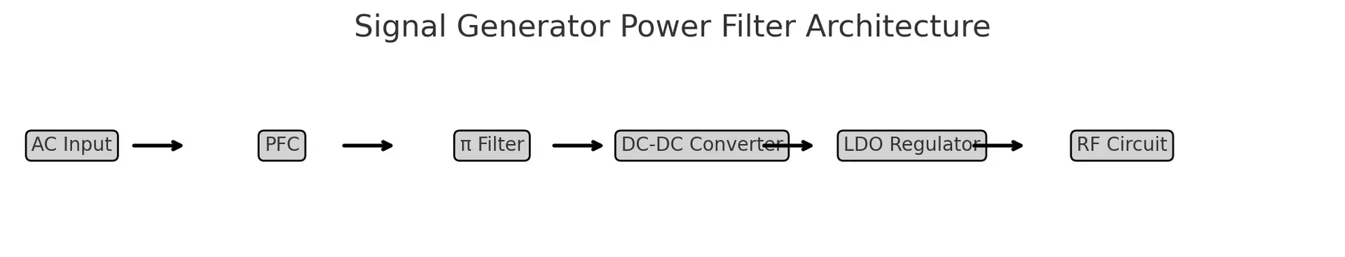
To achieve power supply ripple levels below 5mVp-p, modern signal generators adopt a multi-stage filtering architecture, as illustrated in the diagram below:
Figure: Signal Generator Power Filter Architecture
-
PFC (Power Factor Correction): Shapes the input current waveform and improves efficiency.
-
π Filter Stage: Attenuates high-frequency switching noise and differential mode EMI.
-
DC-DC Converter (Switching Pre-Regulation): Provides voltage transformation and isolation.
-
LDO Regulator: Final linear stage ensures ultra-low noise output (<5mVp-p), critical for LO chain.
Reference: Keysight Technologies, “Designing Low-Noise Power Supplies for RF Instruments”
Download Whitepaper
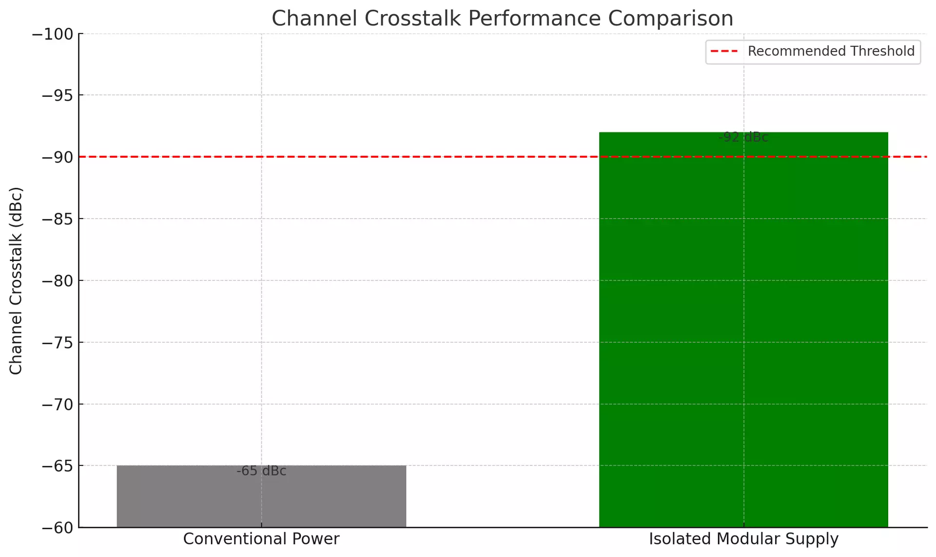
3.2 Isolation to Prevent Channel Crosstalk
For multi-channel digital modulation sources, power rail isolation is essential to prevent cross-channel modulation distortion. Each signal path typically receives its own isolated DC-DC power supply, designed with:
-
Transformers with split bobbin or shielded cores
-
High common-mode rejection filters
-
Careful PCB layout with independent ground planes
Performance Comparison:
| System Type | Crosstalk Level |
|---|---|
| Traditional Power Supply | –65 dBc |
| Modular Isolated Supply | –92 dBc ✅ |
(See Figure: Channel Crosstalk Performance Comparison)
Data Source: Rohde & Schwarz White Paper, “Power Integrity in Microwave Signal Generators”
Source
3.3 Application Case Studies
| Use Case | Power Design Details |
|---|---|
| Microwave Signal Generator | Hybrid SMPS + LDO, ripple <5mVp-p, supports >40GHz, output impedance <10mΩ |
| Field-Portable Generator | AC input: 85–264V wide range, integrated Li-ion backup battery (runtime ≥ 4 hrs) |
| High-Power RF Amplifier | 5kW water-cooled DC system, interleaved phase topology, >90% efficiency |
These systems must be rugged, lightweight, and EMI-quiet – all characteristics where modular power systems significantly outperform conventional linear PSUs.
4. Power Design for Oscilloscopes and Precision Measurement Equipment
Modern high-performance oscilloscopes used in military and aerospace testing require ultra-low noise, multi-domain power isolation, and extreme stability to ensure accurate waveform capture under harsh conditions. These requirements are especially critical in high-bandwidth models (>1 GHz) used for electromagnetic pulse (EMP) characterization, underwater acoustic signature analysis, and aerospace flight data recording.
4.1 Core Power Demands in High-Bandwidth Oscilloscopes
1. Noise Suppression at the Microvolt Level
Noise from power supplies directly impacts the oscilloscope’s vertical resolution, especially when ADCs exceed 12 bits.
Example: To maintain 12-bit resolution at a 1V full-scale range, each LSB equals ≈ 244 µV.
If power supply ripple or ground noise exceeds 10–20 µV, resolution is compromised.
Techniques:
-
Multilayer PCB stack-ups with analog/digital plane separation
-
Magnetic bead filtering at each power domain entry point
-
Point-of-load (POL) regulators placed close to sensitive ADC circuits
2. Bandwidth vs Noise Trade-off
The noise spectral density typically increases with bandwidth, due to wider input noise integration range. Below is the trend:
| Bandwidth (MHz) | Noise Spectral Density (μV/√Hz) |
|---|---|
| 100 | 1.0 |
| 500 | 1.3 |
| 1000 | 1.8 |
| 2000 | 2.5 |
| 4000 | 3.6 |
| 6000 | 4.4 |
| 8000 | 5.2 |
🔎 Interpretation: As bandwidth increases from 100 MHz to 8 GHz, the noise floor rises over 5×, demanding stricter noise suppression from the power system.
4.2 Power Domain Isolation Strategy
To prevent signal coupling between analog front-end (AFE), digital processing, and high-resolution display systems, modern scopes deploy independent power domains.
Power Isolation Architecture Overview:
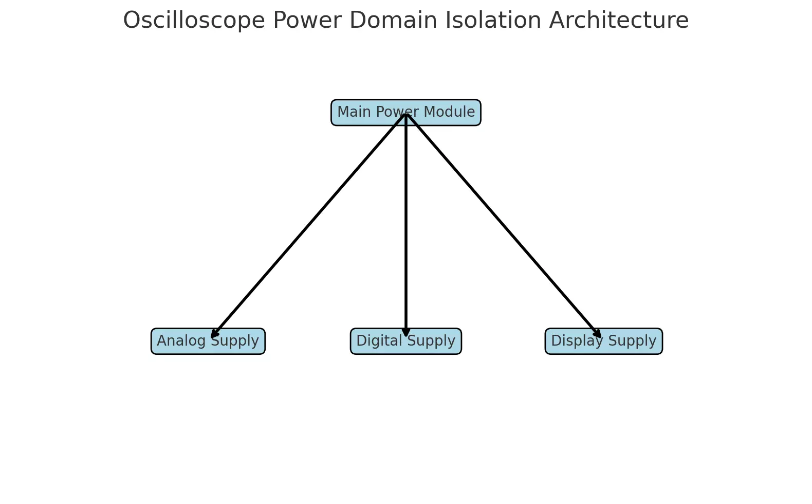
(Refer to previous diagram: “Oscilloscope Power Domain Isolation Architecture”)
-
Analog Domain: ±12V low-noise supply with <3 μV/√Hz density
-
Digital Domain: +3.3V / +1.8V switching supply, heavily filtered for EMI
-
Display Domain: Separate +12V or +24V rail to avoid introducing flicker or modulation into AFE
4.3 Military-Specific Oscilloscope Applications
| Use Case | Design Feature |
|---|---|
| EMP Test Scopes | Shielded power input, survives 50 kV/m transient field strength (MIL-STD-461G) |
| Underwater Weapon Monitoring | IP68-sealed power supply, operational to 500m depth for 30+ days continuously |
| Aerospace Avionics Platforms | Power system certified to DO-160G, full operation –55°C to +85°C, 70,000 ft alt. |
Reference: Tektronix Military Oscilloscope Power Design Notes
Download PDF
5.1 Decision Tree for Power Module Selection
🔧 Step-by-Step Criteria:
-
Electrical Performance
-
Efficiency ≥ 90%
-
Ripple < 10mVp-p (or <5μV/√Hz for sensitive loads)
-
Transient response < 100μs (25–75% load step)
-
-
Environmental Compatibility
-
MIL-STD-810H (vibration, shock, thermal cycling)
-
MIL-STD-461G (EMI/EMC)
-
IP68 / DO-160G for specific domains (underwater, avionics)
-
-
System-Level Factors
-
Redundancy requirements (N+1)
-
Scalability (modular parallel/series connection)
-
Weight & form factor (especially airborne/portable systems)
-
-
Lifecycle Cost (TCO)
-
Efficiency loss cost over 10 years
-
MTBF > 100,000 hours to reduce maintenance cycles
-
AI/diagnostic features for predictive maintenance
-
5.2 TCO Model: Conventional vs Modular Power
| Item | Traditional PSU | Modular Power Supply |
|---|---|---|
| Initial Cost (USD) | $800 | $1200 |
| Annual Power Loss (W @ 85%) | 200 | 80 |
| 10-Year Energy Cost | ~$2200 | ~$880 |
| Maintenance Downtime | 5× / 10 years | 1× / 10 years |
| Total Cost of Ownership (TCO) | ~$4200 | ~$2580 ✅ |
📘 Source: U.S. DoD Power Efficiency Metrics Guidebook, 2022 Edition
(Link)
5.3 Next-Gen Technology: GaN, SiC & Intelligent Power
GaN/SiC Power Devices:
-
Enable MHz-level switching
-
Reduce transformer/inductor volume >60%
-
Increase power density to >300W/in³
-
Improve thermal performance with low Rds(on)
AI-Enabled Smart Modules:
-
Built-in telemetry (voltage, current, temperature)
-
Support for predictive fault detection
-
Adaptive control algorithms for variable loads
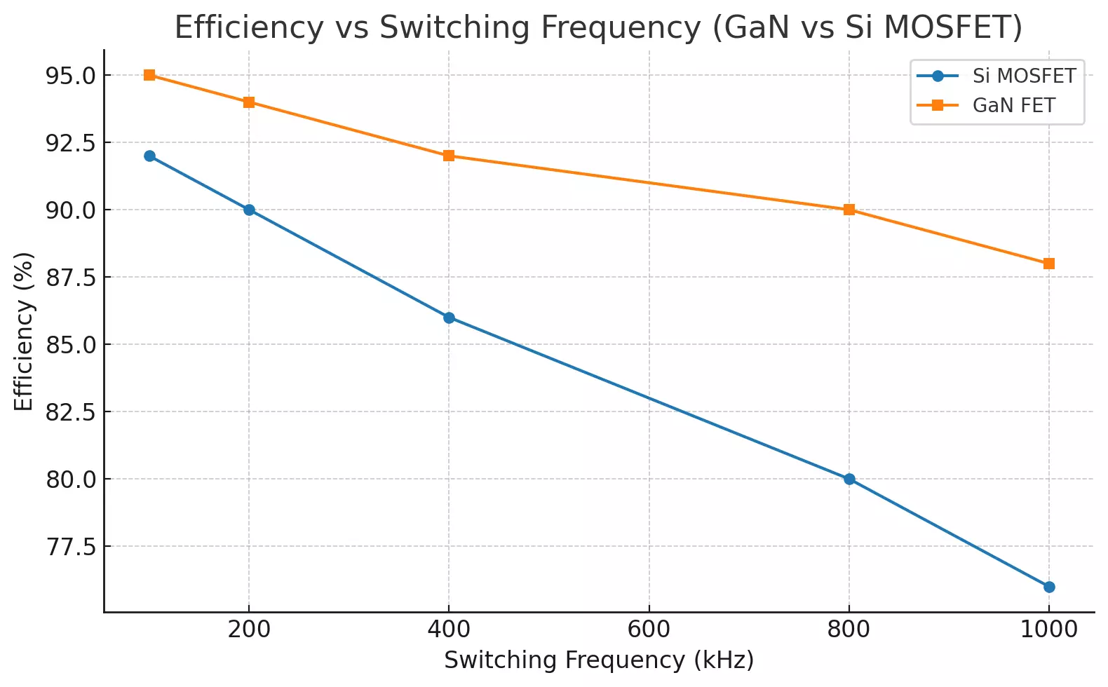
🔍 Efficiency vs Frequency Comparison:
(Refer to previous graph: "GaN vs Si MOSFET Efficiency")
-
GaN retains ≥88% efficiency at 1MHz
-
Si MOSFET drops below 80% beyond 800kHz
-
This makes GaN ideal for SWaP-constrained military platforms (Size, Weight, and Power)
Reference: Power Electronics News, “How GaN is Revolutionizing Military Power Supply Design”
Read Article
✅ 6. Conclusion
From phase-array radar to RF signal generators and high-precision oscilloscopes, military-grade testing equipment demands mission-critical reliability, minimal electrical noise, and robust environmental resilience. Modular power supplies deliver these capabilities while enabling scalability, maintainability, and future-readiness through GaN/SiC technology and intelligent diagnostics.
As modular design becomes the new baseline in defense R&D labs, the power supply is no longer a background component—it’s a strategic enabler of next-generation test and signal systems.